How to design high current busbars for different frequencies?
Sep 11, 2025
Leave a message
Hey there! As a supplier of high current busbars, I've seen firsthand the importance of getting the design right, especially when it comes to different frequencies. In this blog, I'm gonna share some tips on how to design high current busbars for various frequencies.
Understanding the Basics
Before we dive into the design process, let's quickly go over some basic concepts. Busbars are conductors that are used to carry large amounts of electrical current. They're commonly found in electrical distribution systems, power generation plants, and industrial facilities. When it comes to high current applications, the design of the busbar becomes crucial to ensure efficient and safe operation.


One of the key factors that affects busbar design is frequency. Different frequencies can have a significant impact on the performance of the busbar. For example, at high frequencies, the skin effect becomes more pronounced. The skin effect causes the current to flow mainly on the surface of the conductor, which increases the effective resistance of the busbar. This can lead to higher power losses and increased heating.
Design Considerations for Different Frequencies
Low Frequencies (50 - 60 Hz)
At low frequencies, such as the standard 50 or 60 Hz used in most power distribution systems, the skin effect is relatively small. However, we still need to consider other factors like current-carrying capacity, mechanical strength, and thermal management.
- Current-Carrying Capacity: The first step in designing a busbar is to determine the required current-carrying capacity. This depends on the load that the busbar will be supplying. We need to select a busbar with a cross-sectional area that can handle the expected current without overheating. For example, if we're designing a busbar for a large industrial motor, we'll need to calculate the motor's full-load current and then choose a busbar that can safely carry that current.
- Mechanical Strength: Busbars need to be able to withstand mechanical stresses, such as vibrations and shocks. We usually use copper or aluminum as the conductor material because they have good mechanical properties. The shape and size of the busbar also play a role in its mechanical strength. For instance, a rectangular busbar is more rigid than a flat one and can better resist bending forces.
- Thermal Management: Even at low frequencies, heat is generated in the busbar due to the resistance of the conductor. We need to ensure that the busbar has proper ventilation and cooling to prevent overheating. This can involve using heat sinks or fans to dissipate the heat.
Medium Frequencies (100 Hz - 10 kHz)
As the frequency increases into the medium range, the skin effect starts to become more noticeable. This means that we need to pay more attention to the surface area of the busbar.
- Surface Area: To reduce the impact of the skin effect, we can increase the surface area of the busbar. One way to do this is by using multiple parallel conductors instead of a single large one. This spreads the current over a larger surface area, reducing the effective resistance. For example, instead of using a single thick copper bar, we can use several thinner bars connected in parallel.
- Material Selection: At medium frequencies, the choice of material becomes more critical. Copper is often preferred over aluminum because it has a lower resistivity and better conductivity. Additionally, we can use materials with special coatings or treatments to improve the surface conductivity.
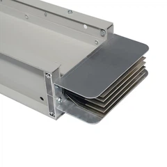
- Insulation: As the frequency increases, the insulation requirements for the busbar also change. We need to use insulation materials that can withstand the higher electrical stresses associated with medium frequencies. Sandwich Bus Duct Insulation is a great option as it provides good insulation and mechanical protection.
High Frequencies (10 kHz - 1 MHz)
At high frequencies, the skin effect is very significant, and other factors like proximity effect also come into play. The proximity effect causes the current distribution in the busbar to be uneven when there are other nearby conductors.
- Litz Wire: For high-frequency applications, we often use litz wire. Litz wire consists of multiple small insulated strands that are twisted together in a specific pattern. This helps to reduce the skin effect and proximity effect by increasing the effective surface area of the conductor and minimizing the magnetic coupling between the strands.
- Geometry Optimization: The shape and layout of the busbar are crucial at high frequencies. We need to design the busbar in a way that minimizes the magnetic fields and reduces the coupling between different parts of the conductor. For example, we can use a spiral or zigzag shape to reduce the inductance and improve the high-frequency performance.
- Cooling: High-frequency busbars generate a lot of heat due to the increased power losses. We need to implement advanced cooling techniques, such as liquid cooling or forced air cooling, to keep the temperature within acceptable limits.
Design Tools and Software
Designing high current busbars for different frequencies can be a complex task. Fortunately, there are several design tools and software available that can help us with the process.
- Finite Element Analysis (FEA) Software: FEA software allows us to simulate the electrical and thermal behavior of the busbar. We can use it to analyze the current distribution, temperature rise, and magnetic fields in the busbar. This helps us to optimize the design and ensure that it meets the required specifications.
- Busbar Design Calculators: There are also online calculators available that can help us calculate the current-carrying capacity, resistance, and other parameters of the busbar. These calculators are based on industry standards and formulas and can save us a lot of time and effort.
Case Studies
Let's take a look at a couple of real-world examples to see how these design principles are applied.
Case Study 1: A Power Distribution System at 60 Hz
We were approached by a large commercial building to design a busbar system for their power distribution. The system needed to carry a maximum current of 2000 A at 60 Hz. We selected a rectangular copper busbar with a cross-sectional area of 2000 mm². To ensure proper thermal management, we installed heat sinks and provided adequate ventilation in the busbar enclosure. After installation, the busbar system performed well, with minimal power losses and no overheating issues.
Case Study 2: A Medium-Frequency Induction Heating System
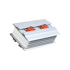
A customer was developing an induction heating system that operated at 5 kHz. The busbar needed to carry a high current while minimizing power losses. We used multiple parallel copper bars to increase the surface area and reduce the skin effect. We also used Busway Vertical Elbow to optimize the layout and reduce the inductance. The final design met the customer's requirements and improved the efficiency of the induction heating system.
Conclusion
Designing high current busbars for different frequencies is a challenging but rewarding task. By understanding the basic principles and considering the specific requirements of each frequency range, we can design busbars that are efficient, reliable, and safe. Whether you're working on a low-frequency power distribution system or a high-frequency industrial application, the right design can make all the difference.
If you're in the market for high current busbars and need expert advice on designing them for your specific frequency requirements, don't hesitate to reach out. We're here to help you find the best solution for your project. Whether it's a 4000a Bus Duct or a custom-designed busbar, we have the expertise and experience to deliver high-quality products. Contact us today to start the conversation and get a quote for your next project.
References
- Grover, F. W. (1946). Inductance Calculations: Working Formulas and Tables. Dover Publications.
- Chapman, S. J. (2012). Electric Machinery Fundamentals. McGraw-Hill Education.
- IEC 60439-1: Low-voltage switchgear and controlgear assemblies - Part 1: Type-tested and partially type-tested assemblies.
Send Inquiry