

What are the effects of frequency on high current busbars?
Oct 14, 2026
Leave a message
In the realm of electrical power distribution, high current busbars play a pivotal role in efficiently transmitting large amounts of electrical energy. As a leading high current busbar supplier, we understand the critical factors that affect the performance of these essential components. One such factor that significantly impacts high current busbars is frequency. In this blog, we will explore the various effects of frequency on high current busbars and how it influences their design, operation, and overall performance.
Skin Effect
One of the most well - known effects of frequency on high current busbars is the skin effect. At low frequencies, the current is uniformly distributed across the cross - section of the busbar. However, as the frequency increases, the alternating magnetic field generated by the current induces eddy currents within the busbar. These eddy currents oppose the flow of the original current, causing the current to flow more towards the outer surface of the busbar.
Mathematically, the skin depth (δ), which is the distance from the surface of the conductor where the current density has decreased to 1/e (about 37%) of its value at the surface, is given by the formula:
[ \delta=\sqrt{\frac{2\rho}{\omega\mu}} ]
where (\rho) is the resistivity of the conductor material, (\omega = 2\pi f) is the angular frequency, and (\mu) is the magnetic permeability of the conductor material. As the frequency (f) increases, the skin depth (\delta) decreases.
For high current busbars, the skin effect has several implications. Firstly, it effectively reduces the cross - sectional area available for current flow. This means that for a given current, the current density at the outer surface of the busbar increases, leading to higher resistive losses ((P = I^{2}R)). These losses manifest as heat, which can cause thermal stress on the busbar and its associated components. To mitigate the skin effect, busbars used at high frequencies are often designed with a larger surface area, such as flat or laminated busbars.
Proximity Effect
The proximity effect is closely related to the skin effect and also arises due to the interaction of magnetic fields. When multiple busbars are placed in close proximity to each other, the magnetic field of one busbar affects the current distribution in the adjacent busbars. At high frequencies, the proximity effect can cause the current to be concentrated in certain regions of the busbars, leading to uneven current distribution.
Similar to the skin effect, the proximity effect can increase the effective resistance of the busbars, resulting in higher power losses. In a high - current busbar system, where multiple busbars are often used in parallel to carry large currents, the proximity effect can be a significant concern. Designers need to carefully consider the spacing between the busbars and their arrangement to minimize the impact of the proximity effect. For example, using proper insulation between busbars and maintaining an appropriate distance can help reduce the magnetic coupling and thus the proximity effect.
Inductive Reactance
The inductive reactance ((X_{L})) of a busbar is given by the formula (X_{L}=\omega L = 2\pi fL), where (L) is the inductance of the busbar and (f) is the frequency. As the frequency increases, the inductive reactance of the busbar also increases.
In a high current busbar system, the increase in inductive reactance can have several consequences. Firstly, it leads to a phase shift between the voltage and current in the busbar. This phase shift can cause power factor issues, as the power factor ((PF=\cos\theta), where (\theta) is the phase angle between voltage and current) decreases with an increase in the phase shift. A low power factor means that more apparent power ((S = VI)) is required to deliver the same amount of real power ((P = VI\cos\theta)), resulting in higher energy losses in the electrical system.
Secondly, the high inductive reactance can cause voltage drops along the busbar. In a power distribution system, voltage drops can affect the performance of electrical equipment connected to the busbar. For sensitive equipment, even a small voltage drop can lead to malfunctions or reduced efficiency. To address the issue of inductive reactance, busbars can be designed with lower inductance, for example, by using a more compact layout or by using materials with low magnetic permeability.
Dielectric Losses
In high current busbar systems, insulation materials are used to separate the busbars and prevent electrical short - circuits. At high frequencies, the dielectric materials used in the insulation can experience losses due to the alternating electric field. These losses are known as dielectric losses.
The dielectric loss factor ((\tan\delta)) is a measure of the efficiency of a dielectric material in storing and dissipating electrical energy. As the frequency increases, the dielectric loss factor of the insulation material may increase, leading to higher power losses in the insulation. These losses can cause heating of the insulation, which can degrade the insulation material over time and reduce its effectiveness.
To minimize dielectric losses, high - quality insulation materials with low dielectric loss factors are used in high - frequency high current busbar systems. Additionally, proper design and installation of the insulation can help reduce the impact of dielectric losses.
Impact on Design and Selection of Busbars
The effects of frequency on high current busbars have a profound impact on their design and selection. For high - frequency applications, busbars need to be designed to minimize the skin effect, proximity effect, inductive reactance, and dielectric losses.
- Material Selection: Materials with high conductivity and low magnetic permeability are preferred for high - frequency busbars. For example, copper is a commonly used material due to its high electrical conductivity. Additionally, some alloys may be used to further improve the performance of the busbar.
- Geometry: The geometry of the busbar is crucial for high - frequency applications. Flat or laminated busbars are often used to increase the surface area and reduce the skin effect. The spacing between multiple busbars also needs to be carefully designed to minimize the proximity effect.
- Insulation: High - quality insulation materials with low dielectric loss factors are essential for high - frequency busbar systems. The insulation should also be able to withstand the thermal stress caused by the various losses in the busbar.
Our Offerings as a High Current Busbar Supplier
As a trusted high current busbar supplier, we are well - aware of the challenges posed by frequency on busbar performance. We offer a wide range of busbar products that are designed to meet the requirements of different frequency applications.
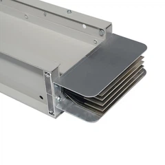
Our Rising Mains Bus Duct is a high - quality solution for vertical power distribution in buildings. It is designed to minimize the effects of frequency, ensuring efficient and reliable power transmission. The bus duct is made of high - conductivity materials and uses advanced insulation techniques to reduce losses and improve performance.
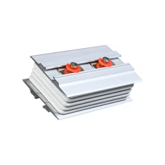
Our Bus Duct Flange is an important component in busbar systems. It is designed to provide a secure and reliable connection between bus ducts, while also minimizing the impact of frequency - related effects. The flange is made of materials with appropriate electrical and mechanical properties, ensuring long - term performance.
We also offer 3 Phase Busbar Trunking for three - phase power distribution. This product is carefully designed to handle high currents and high frequencies, with a focus on reducing losses and improving power factor.
Contact Us for Your Busbar Needs
If you are in need of high - quality high current busbars for your electrical power distribution project, we invite you to contact us. Our team of experts can provide you with detailed information about our products, help you select the right busbar solution for your specific frequency requirements, and offer technical support throughout the installation and operation process.
We understand the importance of reliable and efficient power distribution, and we are committed to providing you with the best busbar products and services. Whether you are working on a small - scale project or a large industrial installation, we have the expertise and resources to meet your needs.


References
- Grover, F. W. (1946). Inductance Calculations: Working Formulas and Tables. Dover Publications.
- Dorf, R. C., & Svoboda, J. A. (2014). Introduction to Electric Circuits. Wiley.
- Chapman, S. J. (2012). Electric Machinery Fundamentals. McGraw - Hill.
Send Inquiry