

How to calculate the power - distribution capacity of Aluminum Bus Duct?
Oct 15, 2025
Leave a message
Hey there! As a supplier of Aluminum Bus Duct, I often get asked about how to calculate the power - distribution capacity of these bus ducts. It's a crucial topic, especially for those in the electrical industry who need to ensure efficient and safe power distribution. In this blog, I'll walk you through the process step by step.
Understanding the Basics of Aluminum Bus Duct
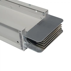
Before we dive into the calculations, let's quickly go over what Aluminum Bus Duct is. It's a system used for distributing electric power. Instead of using traditional cables, bus ducts consist of aluminum conductors enclosed in a protective housing. They're known for their high current - carrying capacity, low impedance, and easy installation.
Factors Affecting Power - Distribution Capacity
Several factors play a role in determining the power - distribution capacity of Aluminum Bus Duct.
1. Conductor Size
The size of the aluminum conductors is a major factor. Larger conductors can carry more current. The cross - sectional area of the conductor is usually measured in square millimeters or square inches. A bigger cross - sectional area means less resistance, which in turn allows more current to flow without excessive heating.
2. Temperature Rise
When current flows through the bus duct, it generates heat. The allowable temperature rise of the bus duct affects its capacity. Most bus ducts are designed to operate within a certain temperature range. If the temperature rises too high, it can lead to insulation damage and reduce the lifespan of the bus duct.
3. Ambient Temperature
The temperature of the surrounding environment also matters. If the ambient temperature is high, the bus duct will have less capacity to handle additional heat generated by the current. For example, a bus duct installed in a hot factory will have a lower power - distribution capacity compared to one installed in a cooler environment.
4. Installation Method
The way the bus duct is installed can impact its performance. Proper ventilation is essential to dissipate heat. If the bus duct is installed in a confined space with poor ventilation, the heat will build up, reducing its capacity.
Calculating the Power - Distribution Capacity
Step 1: Determine the Load Requirements
First, you need to figure out the electrical load that the bus duct will need to support. This involves adding up the power ratings of all the electrical devices that will be connected to the bus duct. For example, if you have several motors and lighting fixtures, calculate the total power consumption in kilowatts (kW).
Step 2: Calculate the Current
Once you know the load in kilowatts, you can calculate the current using the formula (I=\frac{P}{\sqrt{3}\times V\times PF}), where (I) is the current in amperes (A), (P) is the power in kilowatts, (V) is the voltage, and (PF) is the power factor. The power factor is a measure of how effectively the electrical device uses the power. It typically ranges from 0.7 to 0.95.


Step 3: Select the Conductor Size
Based on the calculated current, you need to select an appropriate conductor size. You can refer to the manufacturer's specifications or industry standards. These resources provide tables that show the maximum current - carrying capacity for different conductor sizes. Make sure to choose a conductor size that can handle the calculated current with some margin for safety.
Step 4: Consider Temperature and Ambient Conditions
Adjust the current - carrying capacity of the selected conductor based on the expected temperature rise and ambient temperature. Most manufacturers provide derating factors for different temperature conditions. Multiply the rated current - carrying capacity of the conductor by the derating factor to get the adjusted capacity.
Step 5: Check for Voltage Drop
It's also important to check for voltage drop along the bus duct. Excessive voltage drop can cause problems for the connected electrical devices. You can use the formula (V_d = I\times R\times L), where (V_d) is the voltage drop, (I) is the current, (R) is the resistance per unit length of the bus duct, and (L) is the length of the bus duct.
Using Our Aluminum Bus Duct Products
At our company, we offer a wide range of high - quality Aluminum Bus Duct products. Our High Current Busbar is designed to handle large currents efficiently. It has a low impedance design, which reduces power losses and ensures reliable power distribution.
If you need to change the direction of the bus duct, our Busway Vertical Elbow and Busway Horizontal Elbow are great options. They are easy to install and maintain, and they maintain the electrical performance of the bus duct system.
Conclusion
Calculating the power - distribution capacity of Aluminum Bus Duct is a multi - step process that requires careful consideration of various factors. By following the steps outlined in this blog, you can ensure that you select the right bus duct for your electrical system.
If you're in the market for Aluminum Bus Duct products, we'd love to hear from you. Whether you have questions about our products or need help with your power - distribution calculations, our team of experts is here to assist you. Don't hesitate to reach out for a quote or to start a discussion about your specific requirements.
References
- Electrical Installation Handbook, Schneider Electric
- National Electrical Code (NEC)
- IEEE Standards for Power Distribution Systems
Send Inquiry