

How to calculate the power capacity of a Busway Feeder Box?
Dec 08, 2025
Leave a message
Calculating the power capacity of a Busway Feeder Box is a crucial task that requires a comprehensive understanding of electrical principles and the specific characteristics of the equipment. As a supplier of Busway Feeder Boxes, I am well - versed in this process and would like to share some valuable insights with you.
Understanding the Basics of Busway Feeder Boxes
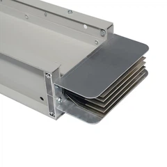
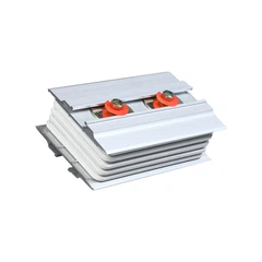
A Busway Feeder Box is an essential component in electrical distribution systems. It serves as a connection point between the main busway and the branch circuits, allowing for the efficient transfer of electrical power. The power capacity of a Busway Feeder Box determines the amount of electrical load it can safely handle.
Factors Affecting the Power Capacity
1. Busbar Material and Size
The material and size of the busbars inside the Busway Feeder Box play a significant role in determining its power capacity. Tinned Copper Busbar is a popular choice due to its excellent electrical conductivity and corrosion resistance. The cross - sectional area of the busbar is directly related to its current - carrying capacity. A larger cross - sectional area can carry more current without overheating. For example, a busbar with a larger cross - section will have a lower resistance, which in turn reduces power losses and allows for higher power transfer.
2. Insulation Material
The insulation material used in the Busway Feeder Box is another critical factor. High - Insulation Polyester Film provides reliable insulation, preventing electrical leakage and short - circuits. Good insulation also helps to maintain the temperature of the busbars within safe limits. If the insulation is of poor quality, it can lead to heat build - up, which may reduce the power capacity of the feeder box and pose a safety hazard.
3. Ambient Temperature
The ambient temperature in which the Busway Feeder Box operates affects its power capacity. Higher ambient temperatures can cause the busbars to heat up more quickly. As the temperature of the busbars increases, their resistance also increases, which reduces the amount of current they can carry. For instance, in a hot industrial environment, the power capacity of the feeder box may need to be derated to ensure safe operation.
4. Load Type
The type of load connected to the Busway Feeder Box is also important. Different loads have different power requirements and characteristics. Resistive loads, such as heaters, have a relatively stable power demand. On the other hand, inductive loads, like motors, have a higher inrush current when they start. This inrush current can be several times higher than the normal operating current. When calculating the power capacity, it is necessary to consider the peak current requirements of the load to ensure that the feeder box can handle the load without tripping the protective devices.
Calculation Methods
1. Using the Ampacity Tables
One of the most common methods for calculating the power capacity of a Busway Feeder Box is by referring to ampacity tables. These tables provide the maximum current - carrying capacity of different busbar sizes and materials under specific conditions. For example, the National Electrical Code (NEC) provides ampacity tables that take into account factors such as the type of conductor, insulation, and ambient temperature.
To use the ampacity tables, you first need to determine the size and material of the busbars in the feeder box. Then, based on the ambient temperature and the installation conditions, you can find the corresponding ampacity value from the table. Once you have the ampacity, you can calculate the power capacity using the formula (P = VI), where (P) is the power in watts, (V) is the voltage, and (I) is the current.
2. Consideration of Derating Factors
As mentioned earlier, factors such as ambient temperature, number of conductors in a raceway, and load type may require derating of the ampacity. For example, if the ambient temperature is higher than the standard temperature specified in the ampacity table, you need to apply a derating factor to the ampacity value. The derating factor is usually a percentage that reduces the maximum current - carrying capacity of the busbars.
Let's say the ampacity of a busbar at a standard temperature is (I_{std}), and the derating factor due to high ambient temperature is (D). The derated ampacity (I_{derated}=I_{std}\times D). After obtaining the derated ampacity, you can then calculate the power capacity using the power formula.
3. Accounting for Future Expansion
When calculating the power capacity of a Busway Feeder Box, it is also important to consider future expansion. If there is a possibility of adding more loads in the future, you may need to size the feeder box larger than the current requirements. This can save costs in the long run by avoiding the need for a complete replacement of the feeder box when new loads are added.
Importance of Accurate Calculation
Accurately calculating the power capacity of a Busway Feeder Box is essential for several reasons. Firstly, it ensures the safety of the electrical system. An undersized feeder box can overheat, leading to insulation breakdown, short - circuits, and even fires. Secondly, it helps to optimize the performance of the electrical system. By properly sizing the feeder box, you can minimize power losses and ensure that the electrical load is distributed evenly.
Case Study
Let's consider a case where a manufacturing plant is installing a new electrical distribution system. The plant has a variety of loads, including motors, heaters, and lighting. The electrical engineer needs to calculate the power capacity of the Busway Feeder Box for a particular section of the plant.
The engineer first determines the size and material of the busbars. In this case, Tinned Copper Busbar is selected due to its high conductivity. The ambient temperature in the plant is around 40°C, which is higher than the standard temperature of 30°C used in the ampacity tables.
Using the ampacity tables, the engineer finds the ampacity of the selected busbar size at 30°C. Then, a derating factor of 0.85 is applied to account for the high ambient temperature. The engineer also considers the inrush current of the motors and the total connected load of all the equipment in the section.
After calculating the derated ampacity and considering the load characteristics, the engineer determines the appropriate power capacity of the Busway Feeder Box. This ensures that the feeder box can safely handle the electrical load in the plant and provides room for future expansion.
Conclusion
Calculating the power capacity of a Busway Feeder Box is a complex but essential process. It requires a thorough understanding of electrical principles, consideration of various factors such as busbar material, insulation, ambient temperature, and load type. By using accurate calculation methods and accounting for future expansion, you can ensure the safety and efficiency of your electrical distribution system.


If you are in the market for a high - quality Busway Feeder Box or need assistance with power capacity calculations, we are here to help. Our team of experts has extensive experience in the field and can provide you with the best solutions for your electrical needs. Contact us to start a procurement discussion and find the perfect Busway Feeder Box for your project.
References
- National Electrical Code (NEC)
- Electrical Engineering textbooks on power distribution systems
- Manufacturer's specifications for busbars and insulation materials
Send Inquiry